1kHz 2nd-Order Bessel High-Pass Filter

1kHz 2nd-Order Bessel High-Pass Filter

This filter was designed using TI’s “FilterPro” software. The cutoff frequency and gain can be changed by editing this circuit with new RC values determined by FilterPro. This filter topology is inherently a phase inverting configuration. For a non- inverting low- pass filter use a Sallen- Key type. As shown, this filter is designed for use on a single power supply. For bipolar supplies, Voffset is not needed. Large value resistors– typical in low frequency filters– require a CMOS or JFET input op amp to minimize offset voltage errors. (Circuit is created by Neil P. Albaugh  TI-Tucson)

1kHz 2nd-Order Bessel High-Pass Filter circuit:

2nd oder Bessel LPF

Online Simulation of the “1kHz 2nd-Order Bessel High-Pass Filter” Circuit

The great feature of the TINA circuit simulator that you can analyze this circuit immediately with TINACloud the online version of TINA. Of course you can also run this circuit in the off-line version of TINA.

Click here to invoke TINACloud and analyze the circuit, or watch our tutorial video!

You can send this link to any TINACloud customers and they can immediatelly load it by a single click and then run using TINACloud.

Michael Koltai
www.tina.com

Speech Compression Amplifier With Linear Gain = 20V/V

Speech Compression Amplifier With Linear Gain = 20V/V

Compression amplifiers are frequently used to prevent overmodulation of AM transmitters. This prevents the creation of spurious modulation products called “splatter”. The “soft knee” of the transfer curve also imparts a “vacuum tube- like” sound to audio signals and musical instruments. The brightness of the LEDs indicate the degree of compression.  Bypass capacitors are not shown. (Circuit is created by Neil P. Albaugh,  TI-Tucson)

Speech Compression Amplifier With  Linear Gain = 20V/V circuit:


Speech Compression Amplifier With Linear Gain = 20V/V
Online Simulation of the “Speech Compression Amplifier With  Linear Gain = 20V/V” Circuit

The great feature of the TINA circuit simulator that you can analyze this circuit immediately with TINACloud the online version of TINA. Of course you can also run this circuit in the off-line version of TINA.

Click here to invoke TINACloud and analyze the circuit, or watch our tutorial video!

You can send this link to any TINACloud customers and they can immediatelly load it by a single click and then run using TINACloud.

Michael Koltai
www.tina.com
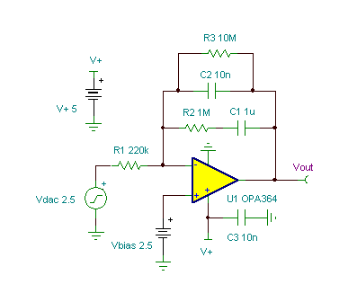
1 kHz Wien-Bridge Oscillator

1 kHz Wien-Bridge Oscillator

The starting pulse is generated by the positive power supply’s startup slope.  If the power supply does not slew fast enough  the oscillator will not start. R3 can be increased to increase the gain and likelihood of starting.  It also increases distortion when  the amplitude as the peaks aproach the power supply rails. (Circuit is created by John Bishop  based on a design by Neil P. Albaugh.)

1 kHz Wien-Bridge Oscillator circuit:
1 khz wien-bridge oscillator
1 kHz Wien-Bridge Oscillator


Online Simulation of the “1 kHz Wien-Bridge Oscillator” Circuit

The great feature of the TINA circuit simulator that you can analyze this circuit immediately with TINACloud the online version of TINA. Of course you can also run this circuit in the off-line version of TINA.

Click here to invoke TINACloud and analyze the circuit, or watch our tutorial video!

You can send this link to any TINACloud customers and they can immediatelly load it by a single click and then run using TINACloud.

Michael Koltai
www.tina.com
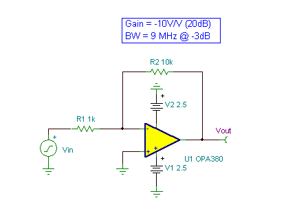
Bridge Sensor Amplifier With RFI Filter

Bridge Sensor Amplifier With RFI Filter

This high accuracy bridge sensor amplifier is based on the autozero INA326 instrumentation amplifier. Bridge sensors are commonly found in pressure transducers, weigh scales, strain guages, and load cells. As shown, the amplifier gain is 200V/V. Capacitors C1 & C2 form a 2nd order 1kHz low- pass filter to reduce noise. The INA326 is virtually free of 1/f noise. R8 & R9 together with C4, C5, & C6 form an RFI filter. For best filtering, make R8 = R9 and C5 = C6 as close as possible. C4 = C5 * 10. In battery- operated applications, an INA327 with shutdown is recommended. For operation over -40C to +125C, use an INA337. (Circuit is created by Neil P. Albaugh,  TI-Tucson)

The “Bridge Sensor Amplifier With RFI Filter” circuit:
Bridge Sensor Amplifier With RFI Filter
Online Simulation of the “Bridge Sensor Amplifier With RFI Filter” Circuit

The great feature of the TINA circuit simulator that you can analyze this circuit immediately with TINACloud the online version of TINA. Of course you can also run this circuit in the off-line version of TINA.

Click here to invoke TINACloud and analyze the circuit, or watch our tutorial video! 

You can send this link to any TINACloud customers and they can immediatelly load it by a single click and then run using TINACloud.

Michael Koltai
www.tina.com
INA154 With Gain-Current Shunt Amplifier

INA154 With Gain-Current Shunt Amplifier

By converting the difference amplifier output to a current source using R2, voltage gain can be achieved with R3. R2 compensates the current sensing resistor R2 and increases the current source output impedance. Resistor R5 compensates for the current shunt resistance R4. Perfect compensation for R4 is not possible since the INA154’s internal resistor network is trimmed for precise ratios rather than absolute  values. A buffer amplifier should be used on the output to prevent gain (loading) error. Bypass capacitors are not shown.  (Circuit is created by Neil P. Albaugh,  TI-Tucson)

INA154 With Gain-Current Shunt Amplifier circuit:
INA154 With Gain-Current Shunt Amplifier circuit
Online Simulation of the “INA154 With Gain-Current Shunt Amplifier” Circuit

The great feature of the TINA circuit simulator that you can analyze this circuit immediately with TINACloud the online version of TINA. Of course you can also run this circuit in the off-line version of TINA.

Click here to invoke TINACloud and analyze the circuit, or watch our tutorial video! 

You can send this link to any TINACloud customers and they can immediatelly load it by a single click and then run using TINACloud.

Michael Koltai
www.tina.com