Bootstrapped Input For High Impedance
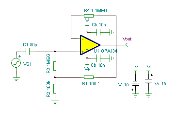
Applying a small amount of positive feedback to the input bias current return resistor R3 effectively raises the apparent input resistance seen by an input signal. Without feedback the input resistance is R3 (1M) in parallel with the input resistance of U1 (1E13 ohms); positive feedback applied through the voltage divider R1 & R2 multiplies the effective input impedance of R3 by creating a smaller differential voltage across the resistor. The pole frequencies of various feedback fractions are illustrated by the AC analysis below. A piezoelectric transducer or condenser microphone is modeled by VG1 in series with capacitor C1. Without bootstrapping (positive feedback), the low- frequency cutoff is 1.8kHz but by placing a 100 ohm resistor at R1, this cut-off frequency drops to 2Hz, illustrating the increased Rin. This does not come without penalty, however. Adding bootstrapping also increases the noise gain of the op amp, multiplying its Vos, drift, and noise. Adding a LARGE capacitor in series with R1 can eliminate the amplified DC offset and drift but the low frequency noise will still suffer. Approach large + feedback fractions with caution; instability and susceptibility to external noise pickup can result. (Circuit is created by Neil P. Albaugh, TI – Tucson)
Bootstrapped Input For High Impedance circuit:

Online Simulation of the “Bootstrapped Input For High Impedance” Circuit
The great feature of the TINA circuit simulator that you can analyze this circuit immediately with TINACloud the online version of TINA. Of course you can also run this circuit in the off-line version of TINA.
Click here to invoke TINACloud and analyze the circuit, or watch our tutorial video!
You can send this link to any TINACloud customers and they can immediatelly load it by a single click and then run using TINACloud.
Michael Koltai
www.tina.com
