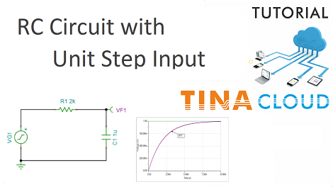
In this tutorial we will create and test an RC integrator circuit with a Unit Step Input.
We create the circuit then we test it by conducting first a Transient analysis, then an AC analysis.
First we make a Transient analysis.
We select Transient from the Analysis menu, then in the Transient dialog window we change the End display parameter to 10m and press Run.
Next, we click again Analysis on the main menu, then select AC Analysis and AC Transfer Characteristic.
In the AC Transfer Characteristic dialog we change the default End frequency to 10k and press Run.
The Diagram window appears, showing the Amplitude of the Transfer function, the Gain of the circuit measured in decibels (dB).
By clicking the tabs at the bottom of the Diagram window, we can also view the Phase, Nyquist, Group Delay and complete Bode diagrams.
We can also see the result of the previous Transient analysis by clicking the Transient 1 tab.
The Diagram window offers numerous other options, including adding labels, cursors, changing curve width, color and more.
You can also add diagrams to the schematics and store them together.
Click here to watch our tutorial video and learn more.
You can learn more about TINA here: www.tina.com
You can learn more about TINACloud here: www.tinacloud.com

