Online Simulation of the Differential Amplifier CMRR Trim Circuit
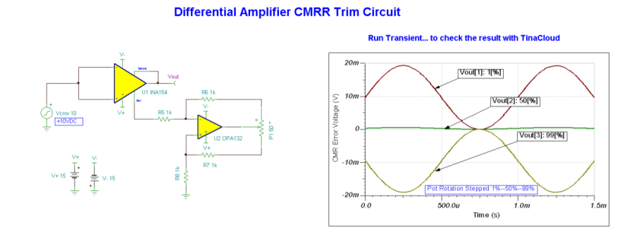
Adding a negative- resistance circuit (U2) to the REF pin allows the CMRR of a differential amplifier or instrumentation amplifier to be trimmed. This is done by applying a sine wave of 20Vp-p to the inputs of U1 and adjusting the potentiometer P1 for a minimum signal at the amplifier output.
By using an AC source the DC input offset errors do not effect this trim.
At 50% rotation of P1 the resistance of R8 cancels the resistance of R5, appearing as a virtual ground to the REF pin. As P1 is adjusted from end to end, R5 is “undercancelled”or “overcancelled” by R8 and the resistance presented to the REF pin goes from a real, positive resistance to a negative resistance. This allows the internal resistor network of U1to be trimmed for maximum CMRR. ( Circuit is created by Neil P. Albaugh TI – Tucson )

Differential Amplifier CMRR Trim Circuit
Online Simulation of the Differential Amplifier CMRR Trim Circuit
The great feature of the TINA circuit simulator that you can analyze this circuit immediately with TINACloud the online version of TINA. Of course you can also run this circuit in the off-line version of TINA.
Click here to invoke TINACloud and analyze the circuit.
You can send this link to any TINACloud customers and they can immediatelly load it by a single click and then run using TINACloud.
Michael Koltai
www.tina.com
