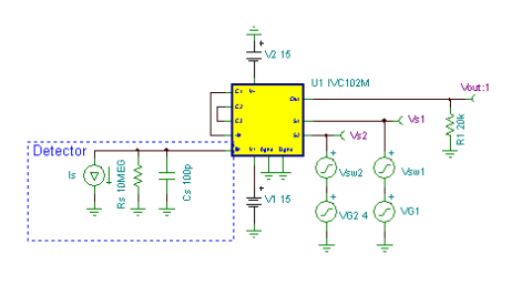
Laser Energy Meter Circuit
An IVC102 switched integrator is also capable of integrating the output of a very fast detector. By storing the energy of a fast detector current pulse on its own capacitance (or on additional capacitance), this energy can then be transfered to the integrator feedback capacitor where it is held until it is sampled and the integrator can then be reset, awaiting the next pulse. Thus laser energy can be measured on a pulse- by- pulse basis. Needless to say, It is necessary to sync the integrator timing with the laser Q- switch. The simulated detector output pulse was 10mA peak with a 10ns width. Charge is stored on Cs until it is transfered when S1 closes.
To prevent droop error due to shunt resistance Rs and the input bias current of U1,
S1 should be closed a few microseconds after the laser pulse. The IVC102 can integrate a positive- output or negative- output detector. Lower sensitivity can be achieved by paralleling C2, C3, or an external capacitance. Bypass capacitors are not shown. (Circuit is created by Neil P. Albaugh TI- Tucson)
Laser Energy Meter circuit:

Online Simulation of the Laser Energy Meter Circuit
The great feature of the TINA circuit simulator that you can analyze this circuit immediately with TINACloud the online version of TINA. Of course you can also run this circuit in the off-line version of TINA.
Click here to invoke TINACloud and analyze the circuit yourself, or watch our tutorial video!
You can send this link to any TINACloud customers and they can immediatelly load it by a single click and then run using TINACloud.
Michael Koltai
www.tina.com
