The rest of this blog is in Hungarian language. You can find the English version here
1. Félösszeadó kapcsolási rajzának létrehozása
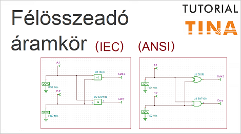
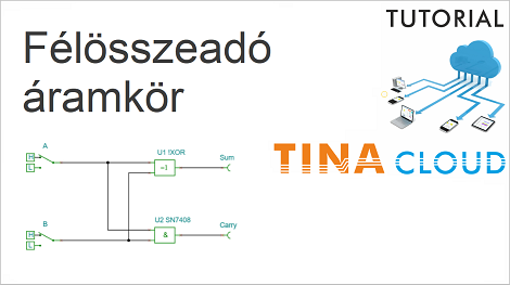
Az alábbiakban egy félösszeadó áramkör létrehozását és szimulációját mutatjuk be a TINA program segítségével.
Ez az oktatóvideó mind az Európában használatos IEC mind pedig az amerikai ANSI szimbólumokkal is elkészült, melyek az alábbi linkekre kattintva érhetők el:
Oktatóvideó: IEC
Oktatóvideó: ANSI
Megjegyezzük hogy logikai komponensekre az amerikai ANSI szimbólumokat Európában és Magyarországon is sokan kedvelik.
Természetesen a TINA és TINACloud programokban bármikor átválthatunk a két szimbólumkészlet bármelyikére.
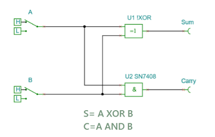
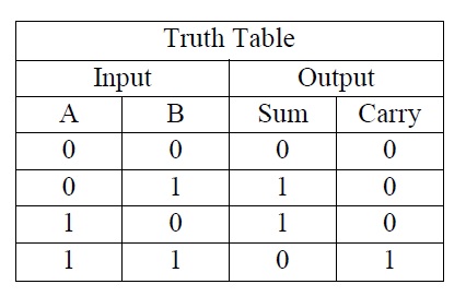
Először létrehozzuk a félösszeadó kapcsolási rajzát. A Sum (összeg) előállításához KIZÁRÓ-VAGY kaput, míg az Carry (átvitel) előállításához ÉS kaput használunk. Bemeneteket High-Low alternatív kapcsolók segítségével állítjuk elő.
2. Félösszeadó áramkör tesztelése DIG Interaktív gomb segítségével
Miután létrehozzuk a Félösszeadó kapcsolási rajzát, teszteljük áramkörünket a DIG Interaktív Digitális gomb megnyomásával.
Abban az esetben, ha a programban más interaktív mód lenne beállítva, akkor kattintsunk az Interaktív menüpontra, és a legördülő listából válasszuk ki a Digitális opciót.
Az interaktív módot úgy is kiválaszthatjuk, ha a DIG interaktív ikon mellett található kis nyílra kattintunk, majd a legördülő listából választjuk ki a Digitális opciót.
3. Alternatív kapcsolók helyettesítése egy-egy digitális jelgenerátorral
Ezt követően töröljük mindkét alternatív kapcsolót, és egy-egy digitális jelgenerátorral helyettesítjük azokat.
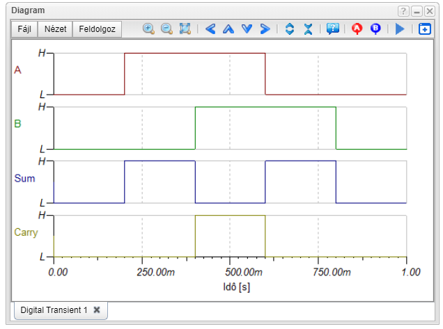
Az összes jelkombináció generálásához 1s időtartamon beállítjuk először a PS1 Digitális Jelgenerátor értékét magas (H) logikai szintre 0.2s és 0.6s között, majd a PS2 Digitális Jelgenerátor értékét 0.4s és 0.8s közötti magas logikai szintre.
Ezek után hozzáadunk még az áramkörünk Bemenetéhez két Kimenetet, hogy a szimulációs eredményeket bemutató diagramunkon a bemeneti jelek is láthatóvá váljanak.
4. Újonnan hozzáadott Kimenetek átnevezése, és sorrendiség meghatározása a diagramban
Átnevezzük az újonnan hozzáadott kimeneteket A-ra és B-re. Még
mielőtt lefuttatnánk a diagramot, meghatározzuk a sorrendiséget.
Ehhez A-t átnevezzük. A:1-re, a B kimenetet B:2-re és a Sum-ot Sum:3-ra.
Ezekkel a beállításokkal tehát meghatározhatjuk a jelek sorrendjét a diagramon A lesz legfelül, ezt követi B, Sum és Carry.
5. Az áramkör tesztelése Digitális Analízis segítségével
Oktatóvideónk végén teszteljük áramkörünket Digitális Analízis segítségével.
A kapott diagramban minden jel külön és a megadott sorrenben szerepel.
Nézze meg videóinkat, melyek az alábbi linkekre kattintva érhetők el.
IEC
ANSI
A következő weboldalakon érhet el minket:
www.tina.com
www.tinacloud.com
Youtube elérhetőségünk: https://www.youtube.com/user/TinaDesignSuite