How to analyze circuits in time domain with TINACloud?

How to analyze circuits in time domain with TINACloud?

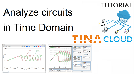
In this tutorial video, we will demonstrate and compare the tools available in TINACloud for analyzing circuits in time domain.

In TINACloud, you can analyze circuits in time domain, employing two different tools:

1.Transient analysis from the Analysis menu of TINACloud.

2.Simulated Virtual Oscilloscope from the T&M menu of TINACloud.

1. Transient Analysis.

First, we analyze the Collpit Oscillator circuit with Transient analysis.

The Transient analysis calculates the time response of circuits and presents the results as diagrams or text.

You have to set the Start Display and End Display parameters.

For COLPITTS.TSC it is preset, but for new circuits, You have to estimate it based on circuit operation.

It is also important to select an option related to the Start condition.

For oscillators, like our circuit, the Zero initial values option applies.

You can refine the diagram in several ways. Here are a few:

  • Zoom into any part of the diagram.
  • Run cursors on the curves of the diagram.
  • Calculate the frequency of the oscillation.
  • Mark a period of the signal with the cursors.
  • You can also find the Local or Global Minimum or Maximum by clicking the actual value field of a curve.
  • Separate the curves or collect them in one diagram.
  • You can insert the diagram into the schematics and save them together.
2. Simulated Virtual Oscilloscope

In practice we very often use an oscilloscope to measure, analyze and debug circuits in the time domain. So, it seems obvious that a simulated oscilloscope can be used in circuit simulation as well.

First, Invoke the Oscilloscope from the T&M menu of TINACloud and then press the Run button.

The Out1 signal appears.

In this video we present how to use the controls to make the curve bigger and more detailed.

Also you can learn about how to stabilize the waveforms on the Oscilloscope, or bring in the Vout signal as well.

We also show how you can fine-tune your circuit until both signals (Out1 and Vout) become sinusoidal.

Finally, we present step by step how you can get the same signal on the Oscilloscope as provided by the previous Transient Analysis.

To watch our tutorial please click  here.

You can learn more about TINA here: www.tina.com

You can learn more about TINACloud here: www.tinacloud.com

How to Create a DC Transfer Characteristic in TINACloud

How to Create a DC Transfer Characteristic in TINACloud

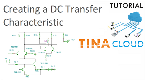
In this short video tutorial, we will show how to create a DC Transfer Characteristic in TINACloud through an example of a differential amplifier circuit.

First we open the DIFFAMP.TSC differential amplifier circuit from the circuit collection of TINACloud, then we select DC Analysis form the Analysis menu.

Next, we click DC Transfer Characteristic…

In the The “Run DC Transfer Analysis” window we select Vin as Input from the Input list. Vin is the name of the generator in the circuit.

We set the Start value and End value of Vin and then we click the Run button.

The DC Transfer Characteristic Diagram appears.

To watch our tutorial please click  here .

You can learn more about TINA here: www.tina.com

You can learn more about TINACloud here: www.tinacloud.com
Creating and Analyzing an RC Circuit with Unit Step Input using TINACloud

Creating and Analyzing an RC Circuit with Unit Step Input using TINACloud

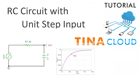
In this tutorial we will create and test an RC integrator circuit with a Unit Step Input.

We create the circuit then we test it by conducting first a Transient analysis, then an AC analysis.

First we make a Transient analysis.

We select Transient from the Analysis menu, then in the Transient dialog window we change the End display parameter to 10m and press Run.

Next, we click again Analysis on the main menu, then select AC Analysis and AC Transfer Characteristic.

In the AC Transfer Characteristic dialog we change the default End frequency to 10k and press Run.

The Diagram window appears, showing the Amplitude of the Transfer function, the Gain of the circuit measured in decibels (dB).

By clicking the tabs at the bottom of the Diagram window, we can also view the Phase, Nyquist, Group Delay and complete Bode diagrams.

We can also see the result of the previous Transient analysis by clicking the Transient 1 tab.

The Diagram window offers numerous other options, including adding labels, cursors, changing curve width, color and more.

You can also add diagrams to the schematics and store them together.

Click here to watch our tutorial video and learn more.

You can learn more about TINA here: www.tina.com

You can learn more about TINACloud here: www.tinacloud.com
What is TINACloud in Hebrew language

What is TINACloud in Hebrew language

? TINACloud מה זה

In this video we will present the highlights of the online circuit simulator software TINACloud translated into Hebrew language.

We will demonstrate the usage of the software through the creation and simulation of an opamp circuit.

We will first create the circuit then test it by AC Analysis.

Click  here  to watch our tutorial video with Hebrew voice-over and subtitles and learn more.

You can learn more about TINA here: www.tina.com

You can learn more about TINACloud here: www.tinacloud.com
What is TINACloud? (Updated version, with integrated Circuit Editor)

What is TINACloud? (Updated version, with integrated Circuit Editor)

TINACloud is the cloud based, multi-language, version of the popular circuit simulation software TINA Design Suite.

You can analyze & design analog, digital, Microcontroller, Switched Mode Power Supply, Radio-Frequency, communication, and optoelectronic circuits.

It also allows you to use manufacturer’s Spice models, hardware description languages and test microcontroller applications in mixed circuit environment.

TINACloud also includes 5 major Hardware Description Languages  (VHDL, Verilog, Verilog A & AMS, SystemC).

Another unique feature of TINACloud is the SYMBOLIC ANALYSIS capability.

TINACloud is extended with the fully integrated PCB Designer of  TINA.

In this tutorial video we will show you how to create and analyze a fourth order active filter circuit using the Spice model of the OPA364 operational amplifier.

Click here to watch our tutorial video and learn more.

You can learn more about TINA here: www.tina.com

You can learn more about TINACloud here: www.tinacloud.com