In our other videos, we have shown how you can create a digital circuit and download to an FPGA board by using TINA’s Schematic Editor. (Programming FPGA boards with TINA using Schematic Design Entry) and the Verilog hardware description language (Programming FPGA boards in Verilog with TINA).
Now, in this video tutorial our circuit, a full adder, will be based on the VHDL hardware description language.
As we stated earlier, TINA works with schematics, but we can also place HDL macros, including VHDL and Verilog, in the design.
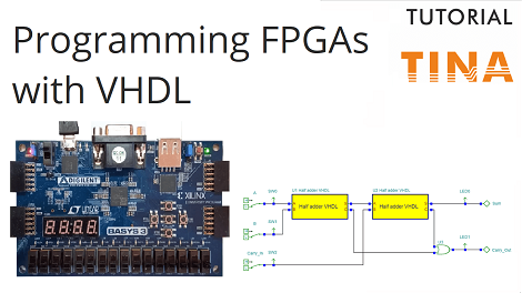
Now, let’s see an example, a full adder using the half-adder VHDL macros.
Start TINA, then open the Full_Adder_VHDL.tsc from the TINA Examples folder.
Most digital circuits that perform addition or subtraction use full adder. This combinational circuit adds two binary digits and a carry-in to produce a sum and carry-out. This one-bit full-adder cell has three inputs (A, B, Carry_In) and two outputs (Sum, Carry_Out) by applying a half adder to accept the carry-in (Carry_In) input from the previous less-significant stage of a multiple bit adder.
The circuit operates like a half adder while the Carry-In value is low.
Start the simulation by pressing the Dig Interactive button.
- When both inputs are low while Carry_In is also low, then Sum and Carry_Out are also low.
- When just one input is low while Carry_In is low, then Sum is high and Carry_Out is also low.
- When both inputs are high when Carry_In is low, then Sum is low and Carry_Out is high.
Now, let’s see what happens when Carry_In is high.
- When Carry_In is High while both inputs are low, then Sum is high too and Carry_Out is low.
- When Carry_In is High while only one input is high then Sum is low and Carry_Out is also high.
- When Carry_In is High while both inputs are high then Sum and Carry_Out are also high.
If Carry_In is high, then the output values change as if we have added one to the full adder.
In the following we will test our circuit in a real environment using the Digilent Basys 3 Artix-7 FPGA Trainer Board.
As it can be seen, this circuit is already prepared for the FPGA Tool export.
(See our previous video: Programming FPGA boards with TINA using Schematic Design Entry)
In the following we will show how to generate the source file for Xilinx Vivado
Finally we will present how our simulated full adder circuit works along with the programmed Basys 3 hardware.
As you can see, in all cases, the results are exactly the same.
This is a great example of demonstrating the power of simulation, since you can test and debug circuits even before realizing them, and in our case before downloading to FPGA, where if there were any issues, it would be extremely hard to find the problem.
Check our other video “Programming FPGA Boards in Verilog with TINA”, where we use a Verilog component in FPGA design.
To learn more please click here.
You can learn more about TINA here: www.tina.com
You can learn more about TINACloud here: www.tinacloud.com

