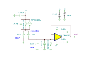
Time to Voltage Converter circuit
Applications such as rangefinders and ballistic chronographs require a high resolution measurement of time. This can be a time period of a few hundred nanoseconds to a few milliseconds. This is an analog circuit that can convert a time period to a voltage with high linearity and high resolution. In principle, a current source is used to charge a capacitor for the time interval and then the voltage across that capacitor is measured. A REF200 precision current source is used to furnish 200uA to a fast SPDT analog switch, represented by SW1 & SW2. This switch steers the current into ground or into a 100pF capacitor C2.
U1 is simply a high- precision buffer amplifier for the voltage on C2.
SW3 is a reset that zeros the voltage on C2. Initially, SW3 is open and SW2 steers the 200uA to ground until a START command is received; SW2 then opens and SW1 closes, steering the current into C2. The capacitor charges until a STOP command is received; SW1 then opens and SW2 closes. The voltage on C2 is proportional to the time between START and STOP; scale time range is determined by the value of C2 so this capacitor should be high quality. A polystyrene or NPO (COG) ceramic is recommended for C2. A small DMOS SD211 can be used for SW3. (Circuit is created by Neil P. Albaugh, TI-Tucson)
Time to Voltage Converter circuit:

Online Simulation of a Time to Voltage Converter circuit:
The great feature of the TINA circuit simulator that you can analyze this circuit immediately with TINACloud the online version of TINA. Of course you can also run this circuit in the off-line version of TINA.
Click here to invoke TINACloud and analyze the circuit yourself or watch our tutorial video!
You can send this link to any TINACloud customers and they can immediatelly load it by a single click and then run using TINACloud.
Michael Koltai
www.tina.com
