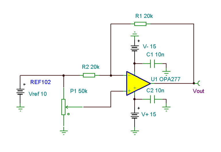
Universal Voltage Reference
“This universal voltage reference circuit”- can provide a reference voltage that is continuously adjustable between -10V and +10V. If a REF02 is substituted for the REF102 shown here, the output range will be -5V to +5V.The circuit uses both an op amp inverting gain path and a non- inverting gain path simultaneously. A potentiometer controls the ratio of these two gain paths. With the potentiometer wiper arm grounded, U1 operates as an ordinary inverting amplifier with a gain of -1V/V. When the wiper arm is rotated to the other end of the potentiometer, however, there is an additional gain path of +2V/V in addition to the -1V/V path. The resulting sum is a gain of +1V/V. At 50% rotation (the wiper arm is exactly centered) the non- inverting gain path drops to +1V/V— cancelling the -1V/V gain entirely. The output is then 0V. P1 should be a good quality potentiometer with high resolution and a good temperature coefficient. Fortunately, the TC match of the resistance ratios of a potentiometer is much lower than its absolute resistance TC. (Circuit is created by Neil P. Albaugh TI- Tucson)
Online Simulation of the Universal Voltage Reference Circuit
The great feature of the TINA circuit simulator that you can analyze this circuit immediately with TINACloud the online version of TINA. Of course you can also run this circuit in the off-line version of TINA.
Click here to invoke TINACloud and analyze the circuit.
You can send this link to any TINACloud customers and they can immediatelly load it by a single click and then run using TINACloud.
Michael Koltai
www.tina.com

