 Click or Tap the Example circuits below to invoke TINACloud and select the Interactive DC mode to Analyze them Online.
 Get a low cost access to TINACloud to edit the examples or create your own circuits
Many circuits are too complex to be solved using the rules for series or parallel circuits or the techniques for conversion to simpler circuits described in previous chapters. For these circuits we need more general solution methods. The most general method is given by Kirchhoff’s laws, which permit the calculation of all circuit voltages and currents of circuits by a solution of a system of linear equations.
There are two Kirchhoff laws, the voltage law and the current law. These two laws can be used to determine all voltages and currents of circuits.
Kirchhoff’s voltage law (KVL) states that the algebraic sum of the voltage rises and voltage drops around a loop must be zero.
A loop in the above definition means a closed path in the circuit; that is, a path that leaves a node in one direction and returns to that same node from another direction.
In our examples, we will use clockwise direction for loops; however, the same results will be obtained if the counterclockwise direction is used.
In order to apply KVL without error, we have to define the so called reference direction. The reference direction of the unknown voltages points from the + to the – sign of the assumed voltages. Imagine using a voltmeter. You would place the voltmeter positive probe (usually red) at the component’s reference + terminal. If the real voltage is positive, it is in the same direction as we assumed, and both our solution and the voltmeter will show a positive value.
When deriving the algebraic sum of the voltages, we must assign a plus sign to those voltages where the reference direction agrees with the direction of the loop, and negative signs in the opposite case.
Another way to state Kirchhoff’s voltage law is: the applied voltage of a series circuit equals the sum of the voltage drops across the series elements.
The following short example shows the use of Kirchhoff’s voltage law.
Find the voltage across resistor R2, given that the source voltage, VS = 100 V and that the voltage across resistor R1 is V1 = 40 V.
The figure below can be created with TINA Pro Version 6 and above, in which drawing tools are available in the schematic editor.
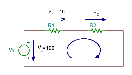

The solution using Kirchhoff’s voltage law: -VS + V1 + V2 =0, or VS = V1 + V2
hence: V2 = VS – V1 = 100-40 = 60V
Note that normally we don’t know the voltages of the resistors (unless we measure them), and we need to use both Kirchhoff’s laws for the solution.
Kirchhoff’s current law (KCL) states that the algebraic sum of all the currents entering and leaving any node in a circuit is zero.
In the following, we give a + sign to currents leaving a node and a – sign to currents entering a node.
Here’s a basic example demonstrating Kirchhoff’s current law.
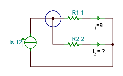

Find the current I2 if the source current IS = 12 A, and I1 = 8 A.
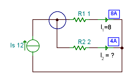

Using Kirchhoff’s current law at the circled node: -IS + I1 + I2 = 0 , hence: I2= IS – I1 = 12 – 8 = 4 A, as you can check using TINA (next figure).
In the next example, we will use both Kirchhoff’s laws plus Ohm’s law to calculate the current and the voltage across the resistors.
In the figure below, you will note the Voltage Arrow above resistors. This is a new component available in Version 6 of TINA and works like a voltmeter. If you connect it across a component, the arrow determines the reference direction (to compare to a voltmeter, imagine placing the red probe at the tail of the arrow and the black probe at the tip). When you run DC analysis, the actual voltage on the component will be displayed on the arrow.
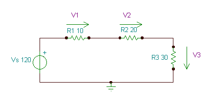

To begin using Kirchhoff’s current law, we see that the currents through all the components are the same, so let’s denote that current by I.
According to Kirchhoff’s voltage law: VS = V1+V2+V3
Now using Ohm’s law: VS=I*R1+ I*R2+I *R3
And from here the current of the circuit:
I=VS /(R1+R2+R3)= 120/(10+20+30) = 2 A
Finally the voltages of the resistors:
V1=I*R1 = 2*10 = 20 V; V2 = I*R2 = 2*20 = 40 V; V3 = I*R3 =2*30 = 60 V
The same results will be seen on the Voltage Arrows by simply running TINA’s interactive DC analysis.
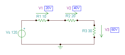

In this next, more complex circuit, we also use both Kirchhoff’s laws and Ohm’s law, but we find that we most solve a linear system of equations.
The total number of independent applications of Kirchhoff’s laws in a circuit is the number of circuit branches, while the total number of unknowns (the current and voltage of each branch) is twice that . However, by also using Ohm’s law at each resistor and the simple equations defining the applied voltages and currents, we get a system of equation where the number of unknowns is the same as the number of equations.
Find the branch currents I1, I2, I3 in the circuit below.
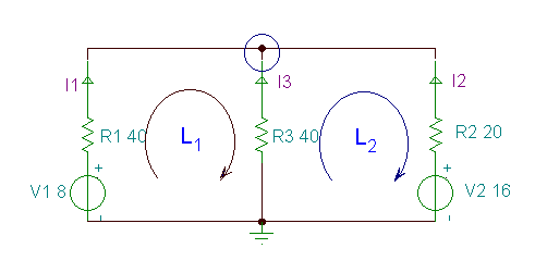

The set of equations follows:
The nodal equation for the circled node:
– I1 – I2 – I3 = 0
or multiplying by -1
I1 + I2 + I3 = 0
The loop equations (using the clockwise direction) for the loop L1, containing V1, R1 and R3
-V1+I1*R1-I3*R3 = 0
and for the loop L2, containing V2, R2 and R3
I3*R3 – I2*R2 +V2 = 0
Substituting the component values:
I1+ I2+ I3 = 0 -8+40*I1 – 40*I3 = 0 40*I3 –20*I2 +16 = 0
Express I1 using the nodal equation: I1 = -I2 – I3
then substitute it into the second equation:
-V1 – (I2 + I3)*R1 –I3*R3 = 0 or –8- (I2 + I3)*40 – I3*40 = 0
Express I2 and substitute it into the third equation, from which you can already calculate I3:
I2 = – (V1 + I3*(R1+R3))/R1 or I2 = -(8 + I3*80)/40
I3*R3 + R2*(V1 + I3*(R1+R3))/R1 +V2 = 0 or I3*40 + 20*(8 + I3*80)/40 + 16 = 0
And: I3 = – (V2 + V1*R2/R1)/(R3+(R1+R3)*R2/R1) or I3 = -(16+8*20/40)/(40 + 80*20/40)
Therefore I3 = – 0.25 A; I2 = -(8-0.25*80)/40 = 0.3 A and I1 = – (0.3-0.25) = – 0.05 A
Or: I1 = -50 mA; I2 = 300 mA; I3 = -250 mA.
Now let’s solve the same equations with TINA’s interpreter:
Sys I1,I2,I3
I1+I2+I3=0
-V1+I1*R1-I3*R3=0
I3*R3-I2*R2+V2=0
end;
I1=[-50m]
I2=[300m]
I3=[-250m]
import numpy as np,sympy as s
#We have a linear system of
#equations that we want to solve:
#I1+I2+I3=0
#-V1+I1*R1-I3*R3=0
#I3*R3-I2*R2+V2=0
I1,I2,I3=s.symbols([‘I1′,’I2′,’I3’])
sol = s.solve([
I1+I2+I3,
-V1+I1*R1-I3*R3,
I3*R3-I2*R2+V2], [I1, I2, I3])
print(sol)
A= np.array([[1,1,1],[R1,0,-R3],[0,-R2,R3]])
b= np.array([0,V1,-V2])
x=np.linalg.solve(A,b)
#I1=x[0]
#I2=x[1]
#I3=x[2]
#I1
print(“I1= %.3f”%x[0])
#I2
print(“I2= %.3f”%x[1])
#I3
print(“I3= %.3f”%x[2])
Finally let’s check the results using TINA:
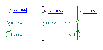

Next, let’s analyze the following even more complex circuit and determine its branch currents and voltages.
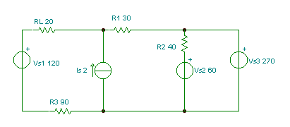

Let’s denote the unknown voltages and currents by adding voltage and current arrows to components, and also show the loops (L1,L2, L3) and the nodes (N1,N2) where we will use the Kirchhoff’s equations.
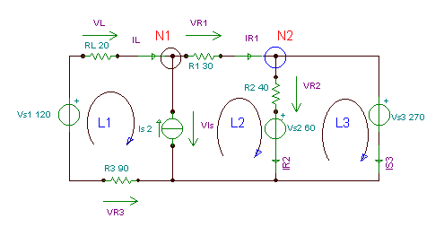  |
Here is the set of Kirchhoff equations for the loops (using the clockwise direction) and the nodes.
-IL + IR1 – Is = 0 (for N1)
– IR1 + IR2 + Is3 = 0 (for N2)
-Vs1 – VR3 + VIs + VL = 0 (for L1)
-VIs + Vs2 +VR2 +VR1 = 0 (for L2)
-VR2 – Vs2 + Vs3 = 0 (for L3)
Applying Ohm’s law:
VL = IL*RL
VR1 =IR1*R1
VR2 = IR2*R2
VR3 = – IL*R3
This is 9 unknowns and 9 equations. The easiest way to solve this is to use TINA’s
interpreter. However, if we are pressed to use hand calculations, we note that this set of equations can be easily reduced to a system of 5 unknowns by substituting the last 4 equations into the L1, L2, L3 loop equations. Also, by adding equations (L1) and (L2), we can eliminate VIs , reducing the problem to a system of 4 equations for 4 unknowns (IL, IR1 IR2, Is3). When we have found these currents, we can easily determine VL , VR1, VR2, and VR3 using the last four equations (Ohm’s law).
Substituting VL ,VR1,VR2 ,VR3 :
-IL + IR1 – Is = 0 (for N1)
– IR1 + IR2 + Is3 = 0 (for N2)
-Vs1 + IL*R3 + VIs + IL*RL = 0 (for L1)
-VIs + Vs2 + IR2*R2 + IR1*R1 = 0 (for L2)
– IR2*R2 – Vs2 + Vs3 = 0 (for L3)
Adding (L1) and (L2) we get
-IL + IR1 – Is = 0 (for N1)
– IR1 + IR2 + Is3 = 0 (for N2)
-Vs1 + IL*R3 + IL*RL + Vs2 + IR2*R2 + IR1*R1 = 0 (L1) + (L2)
– IR2*R2 – Vs2 + Vs3 = 0 (for L3)
After substituting the component values, the solution to these equations comes readily.
-IL+IR1 – 2 = 0 (for N1)
-IR1 + IR2 + IS3 = 0 (for N2)
-120 – + IL*90 + IL*20 + 60 + IR2*40 + IR1*30 = 0 (L1) + (L2)
-IR2*40 – 60 + 270 = 0 (for L3)
from L3 IR2 = 210/40 = 5.25 A (I)
from N2 IS3 – IR1 = – 5.25 (II)
from L1+L2 110 IL + 30 IR1 = -150 (III)
and for N1 IR1 – IL = 2 (IV)
Multiply (IV) by –30 and add to (III) 140 IL = -210 hence IL = – 1.5 A
Substitute IL into (IV) IR1 = 2 + (-1.5) = 0.5 A
and IR1 into (II) IS3 = -5.25 + IR1 = -4,75 A
And the voltages: VR1 = IR1*R1 = 15 V; VR2 = IR2*R2 = 210 V;
VR3 = – IL*R3= 135 V; VL = IL*RL = – 30 V; VIs = VS1+VR3-VL = 285 V
Sys IL,IR1,IR2,Is3,VIs,VL,VR1,VR3,VR2
-IL-Is+IR1=0
-IR1+IR2+Is3=0
-Vs1+VR3+Vis-VL=0
-Vis+VR1+VR2+Vs2=0
-Vs3+VR2+Vs2=0
VR1=IR1*R1
VR2=IR2*R2
VR3=-IL*R3
VL=IL*RL
end;
IL=[-1.5]
IR1=[500m]
IR2=[5.25]
Is3=[-4.75]
VIs=[285]
VL=[-30]
VR1=[15]
VR2=[210]
VR3=[135]
#Ax=b
import numpy as np,sympy as s
#Symbolic solution using numpy.solve
#Equations:
#IL=-Is+IR1
#IR1=IR2+Is3
#Vs1+VR3-Vis-VL=0
#Vis=VR1+VR2+Vs2
#Vs3=VR2+Vs2
#VR1=IR1*R1
#VR2=IR2*R2
#VR3=-IL*R3
#VL=IL*RL
#Solve for:
#IL,IR1,IR2,
#Is3,Vis,VL,
#VR1,VR3,VR2
IL,IR1,IR2,Is3,Vis,VL,VR1,VR3,VR2=s.symbols([‘IL’,’IR1′,’IR2′,’Is3′,’Vis’,’VL’,’VR1′,’VR3′,’VR2′])
sol = s.solve([
-Is+IR1-IL,
IR2+Is3-IR1,
Vs1+VR3-Vis-VL,
VR1+VR2+Vs2-Vis,
VR2+Vs2-Vs3,
IR1*R1-VR1,IR2*R2-VR2,
-IL*R3-VR3,IL*RL-VL],[IL,IR1,IR2,Is3,Vis,VL,VR1,VR3,VR2])
print(sol)
#Another method to solve using numpy.linalg
A=np.array(
[[-1,1,0,0,0,0,0,0,0],
[0,-1,1,1,0,0,0,0,0],
[0,0,0,0,-1,-1,0,1,0],
[0,0,0,0,-1,0,1,0,1],
[0,0,0,0,0,0,0,0,1],
[0,R1,0,0,0,0,-1,0,0],
[0,0,R2,0,0,0,0,0,-1],
[-R3,0,0,0,0,0,0,-1,0],
[RL,0,0,0,0,-1,0,0,0]])
b=np.array([Is,0,-Vs1,-Vs2,Vs3-Vs2,0,0,0,0])
x=np.linalg.solve(A,b)
#IL=x[0] IR1=x[1] IR2=x[2]
#Is3=x[3] Vis=x[4] VL=x[5]
#VR1=x[6] VR2=x[8] VR3=x[7]
print(“IL= %.3f”%x[0])
print(“IR1= %.3f”%x[1])
print(“IR2= %.3f”%x[2])
print(“Is3= %.3f”%x[3])
print(“Vis= %.3f”%x[4])
print(“VL= %.3f”%x[5])
print(“VR1= %.3f”%x[6])
print(“VR2= %.3f”%x[8])
print(“VR3= %.3f”%x[7])
Solution of the reduced set of equations using the interpreter:
| {Solution of the reduced set of equations by TINA’s Interpreter} Sys Il,Ir1,Ir2,Is3 -Il+Ir1-2=0 -Ir1+Ir2+Is3=0 -120+110*Il+60+40*Ir2+30*Ir1=0 -40*Ir2+210=0 end; Il=[-1.5] Ir1=[500m] Ir2=[5.25] Is3=[-4.75] |
We can also enter expressions for the voltages and have TINA’s Interpreter calculate them:
| Il:=-1.5; Ir1:=0.5; Ir2:=5.25; Is3:=-4.75; Vl:=Il*RL; Vr1:=Ir1*R1 Vr2:=Ir2*R2; Vr3:=-Il*R3; VIs:=Vs1-Vl+Vr3; Vl=[-30] Vr1=[15] Vr2=[210] Vr3=[135] VIs=[285] |
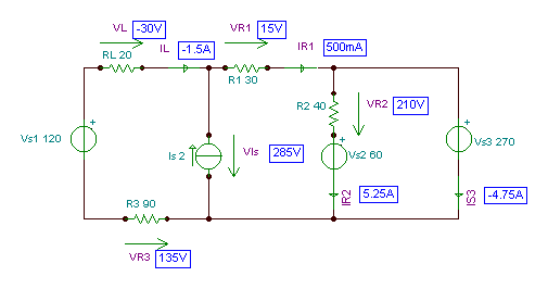  |
We can check the result with TINA by simply turning on TINA’s DC interactive mode or using Analysis / DC Analysis / Nodal Voltages