 Click or Tap the Example circuits below to invoke TINACloud and select the Interactive DC mode to Analyze them Online.
 Get a low cost access to TINACloud to edit the examples or create your own circuits
The Fourier theorem states that any periodic waveform can be synthesized by adding appropriately weighted sine and cosine terms of various frequencies. The theorem is well-covered in other textbooks, so we will only summarize the results and show some examples.
Let our periodic function be f (t) = f (t ±nT) where T is the time of one period and n is an integer number.
w0= 2p/ T the fundamental angular frequency.
By the Fourier theorem, the periodic function can be written as the following sum:

where 
An and Bn are the Fourier coefficients and the sum is the Fourier series.
Another form, probably a bit more practical:

where

A0 = C0 is the DC or average value, A1, B1 and C1 are the fundamental components, and the others are the harmonic terms.
While only a few terms may be required to approximate some waveforms, others will require many terms.
Generally, the more terms included, the better the approximation, but for waveforms containing steps, such as rectangular impulses, the Gibbs phenomenon comes into play. As the number of terms increases, the overshoot becomes concentrated in an ever smaller period of time.
An even function f(t) = f(-t) (axis symmetry) requires only cosine terms.
An odd function f(t) = – f(-t) (point symmetry) requires only sine terms.
A waveform with mirror or half-wave symmetry has only odd harmonics in its Fourier representation.
Here we will not deal with the Fourier series expansion, but will only use a given sum of sines and cosines as an excitation for a circuit.
In the earlier chapters of this book, we dealt with sinusoidal excitation. If the circuit is linear, the superposition theorem is valid. For a network with nonsinusoidal periodic excitation, superposition allows us to calculate the currents and voltages due to each Fourier sinusoid term one at a time. When all are calculated, we finally summarize the harmonic components of the response.
It is a bit complicated to determine the different terms of the periodic voltages and currents and, in fact, it may yield an overload of information. In practice, we would like to simply make measurements. We can measure the different harmonic terms using a harmonic analyzer, spectrum analyzer, wave analyzer or Fourier analyzer. All these are complicated and probably yield more data than needed. Sometimes it is sufficient to describe a periodic signal only by its average values. But there are several kinds of average measurements.
AVERAGE VALUES
Simple average or DC term was seen in the Fourier representation as A0

This average can be measured with instruments such as the Deprez DC instruments.
Effective value or rms (root mean square) has the following definition:

This is the most important average value because the heat dissipated in resistors is proportional to the effective value. Many digital and some analog voltmeters can measure the effective value of voltages and currents.
Absolute average

This average is no longer important; earlier instruments measured this form of average.
If we know the Fourier representation of a voltage or current waveform, we can also calculate the average values as follows:
Simple average or DC term was seen in the Fourier representation as A0 = C0
Effective value or rms (root mean square) is, after integrating the Fourier series of the voltage:

The klirr factor is a very important ratio of the average values:
It is the ratio of the effective value of the higher harmonic terms to the effective value of the fundamental harmonic:


There seems to be a contradiction here–we solve network in terms of harmonic components, but we measure average quantities.
Let us illustrate the method by simple examples:
Example 1
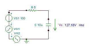
Find the time function and the effective (rms) value of the voltage vC(t)
if R = 5 ohm, C = 10 mF and v(t)=(100 + 200 cos(w0t) + 30 cos(3 w0t – 90°)) V, where the fundamental angular frequency is w0= 30 krad/s.
Try using the superposition theorem to solve the problem.
The first step is to find the transfer function as a function of the frequency. For simplicity, use the substitution: s = j w

Now substitute the component values and s = j k w0where k = 0; 1; 3 in this example and w0= 30 krad/s. In V, A, ohm, mF and Mrad/s units:

It is helpful to use a table to organise the steps of the numerical solution:
k | W(jk) = |
0 |
|
1 |
|
3 |
|
We can summarise the steps of the superposition solution in another table. As we have already seen, to find the complex peak value of a component, we should multiply the complex peak value of the component of the excitation by the value of the complex transfer function:
k | V | W | VCk |
0 | 100 | 1 | 100 |
1 | 200 | 0.55e-j56.3° | 110e-j56.3° |
3 | 30e-j90° | 0.217e-j77.5° | 6.51e-j167.5° |
And finally we can give the time function knowing the complex peak values of the components:
vC(t) = 100 + 110 cos(w0t – 56.3°) + 6.51 cos(3w0t – 167.5°) V
The rms (effective) value of the voltage is:

As you can see, TINA’s measuring instrument measures this rms value.
Example 2
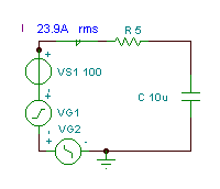
Find the time function and the effective (rms) value of the current i(t)
if R = 5 ohm, C = 10 mF and v(t)=(100 + 200 cos(w0t) + 30 cos(3w0t – 90°)) V where the fundamental angular frequency is w0= 30 krad/s.
Try to solve the problem using the superposition theorem.
  |
The steps of the solution are similar to Example 1, but the transfer function is different.
Now substitute the numerical values and s = j k w0,where k = 0; 1; 3 in this example.
In V, A, ohm, mF and Mrad/s units:

It’s helpful to use a table during the numerical solution:
k | W(jk) = |
0 | |
1 | |
3 | |
We can summarise the steps of the superposition in another table. As we have already seen, to find the peak value of a component, we should multiply the complex peak value of that component of the excitation by the value of the complex transfer function. Use the complex peak values of the components of the excitation:
k | VSk | W(jk) | Ik |
0 | 100 | 0 | 0 |
1 | 200 | 0.162 ej33.7° | 32.4 ej33.7° |
3 | 30 e-j90° | 0.195 ej12.5° | 5.85 e-j77.5° |
And finally, knowing the complex peak values of the components we can state the time function:
i(t) = 32.4 cos (w0t + 33.7°) + 5.85 cos (3w0t – 77.5°) [A]
The rms value of the current:

You can often do a sanity check for part of the solution. For example, a capacitor can have a DC voltage but not a DC current.
Example 3
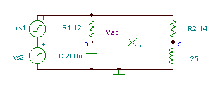
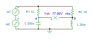
Obtain the time function of the voltage Vab if R1= 12 ohm, R2 = 14 ohm, L = 25 mH, and
C = 200 mF. The generator voltage is v(t)=(50 + 80 cos(w0t) + 30 cos(2 w0t+60°)) V, where the fundamental frequency is f0 = 50 Hz.
The first step is to find the transfer function:

Substituting numerical values in V, A, ohm, mH, mF, kHz units:

Merging the two tables:
| k V Sk |   | V abk |
|---|---|---|
| 0 50 |   | 50 |
| 1 80 |   | 79.3 e-j66.3 |
| 2 30 ej60 |   | 29.7 e-j44.7 |
Finally the time function:
vab(t) = 50 + 79.3 cos(w1t – 66.3°) + 29.7 cos(2w1t – 44.7°) [V]
and the rms value:


