 Click or Tap the Example circuits below to invoke TINACloud and select the Interactive DC mode to Analyze them Online.
 Get a low cost access to TINACloud to edit the examples or create your own circuits
The current in a series circuit has only one path to follow and cannot flow in any other path. Current is exactly the same at every point in a series circuit.

The voltage in a series circuit: the sum of the applied voltages in a series circuit equals the sum of the voltage drops.

From these two principles, it follows that the total resistance in a series resistive circuit is equal to the sum of the individual resistances.

Example 1

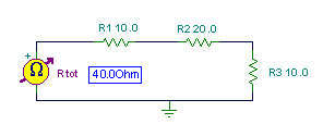
Find the total resistance of the following three resistor circuit:
In the figure above, you can see the result given by TINA.
Now let’s calculate the equivalent series resistance using the formula:

As you can see, the calculated value agrees with TINA’s Ohmmeter.
In electronics you sometimes find circuits where switches are connected in parallel with resistors. When a switch is closed, it shorts out the parallel-connected resistor just as though there were a zero ohm wire in place of the resistor. However, when the switch is open it has no effect on the resistance in parallel with it.
Req:=R1+R2+R3;
Req=[40]
Req=R1+R2+R3
print(“Req=”, Req)
Example 2
Find the total resistance with the switches set as shown:

Rtot = R1 + R2+ R3= 10 + 20+ 15 = 45 ohm.
Req:=R1+R2+R3;
Req=[45]
Req=R1+R2+R3
print(“Req=”, Req)
Example 3
Find the total resistance with the switches set as shown:

Rtot = R1 + R3 = 10 + 15 = 25 ohm.
Req:=R1+R3;
Req=[25]
Req=R1+R3
print(“Req=”, Req)
Example 4

Find the current in the circuit with all possible combinations of closed and open switches and check the result with TINA. Don’t close all the switches at once, or you will short the battery and the fuse will burn out.
I:=VS1/(R1+R2+R3);
I=[100m]
I=VS1/(R1+R2+R3)
print(“I=”, I)
Example 5
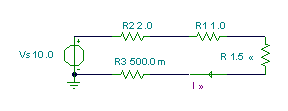
Find the value for R that will result in a current of 2A.

Solution: In order to get the required 2A current with the 20 V source voltage, the total resistance of the circuit must be 10 ohms, since, according to Ohm’s law
I=V/R=20/10=2 A
The total resistance of the circuit is:
Rtot = R1 + R2+ R3 + R = 10 ohm.
Hence R=2 ohm
Req:=Vs/2;
Req=[5]
Ra:=Req-R2-R1-R3;
Ra=[1.5]
Req=Vs/2
print(“Req=”, Req)
Ra=Req-R2-R1-R3
print(“Ra=”, Ra)
Another approach to solving this problem uses one of TINA’s most interesting features, an analysis mode called Optimization. You can set this mode in the Analysis menu, clicking Mode and then setting Optimization. In Optimization, you must define a search region using the Start- and End Value parameters. Using the Analyis menu or the icons at the top right of the screen, you should also set the Optimization Target, which is the value of the current (2A) shown by the Current Arrow. Next, set the Control Object, which in this case is R. After selecting the function, you should click on the respective component (the current arrow or the resistor R) with the special cursor (meter or resistor) appearing after selection of the function.
Finally, TINA’s DC Analysis function will automatically find the exact value of R at which the current will be equal to 2 A.
Try this out by loading the example above and carrying out a DC Analysis from the Analysis menu.
Well, for such a simple circuit, Optimization isn’t necessary, but there are many real world circuits that are far more complex where this feature can save a great deal of hand calculation.