 Click or Tap the Example circuits below to invoke TINACloud and select the Interactive DC mode to Analyze them Online.
 Get a low cost access to TINACloud to edit the examples or create your own circuits
The superposition theorem states that in a linear circuit with several sources, the current and voltage for any element in the circuit is the sum of the currents and voltages produced by each source acting independently.
To calculate the contribution of each source independently, all the other sources must be removed and replaced without affecting the final result. When removing a voltage source, its voltage must be set to zero, which is equivalent to replacing the voltage source with a short circuit. When removing a current source, its current must be set to zero, which is equivalent to replacing the current source with an open circuit.
When you sum the contributions from the sources, you should be careful to take their signs into account. It is best to assign a reference direction to each unknown quantity, if it is not already given.
The total voltage or current is calculated as the algebraic sum of the contributions from the sources. If a contribution from a source has the same direction as the reference direction, it has a positive sign in the sum; if it has the opposite direction, then a negative sign.
Note that If the voltage or current sources have internal resistance, it must remain in the circuit and still be considered. In TINA, you can assign an internal resistance to the DC voltage and current sources, while using the same schematic symbol. Therefore, if you want to illustrate the superposition theorem and at the same time use sources with internal resistance, you should only set the source voltage (or current) to zero, which leaves the source internal resistance intact. Alternatively, you could replace the source with a resistor equal to its internal resistance.
In order to use the superposition theorem with circuit currents and voltages, all of the components must be linear; that is, for all resistive components, the current must be proportional to the applied voltage (satisfying Ohm’s law).
Note that the superposition theorem is not applicable to power, since power is not a linear quantity. The total power delivered to a resistive component must be determined using the total current through or the total voltage across the component and cannot be determined by a simple sum of the powers produced by the sources independently.
Let us illustrate the method of superposition by the following example.
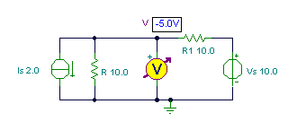

First, calculate V’, the voltage produced by the voltage source VS, using voltage division:
V’ = VS * R / (R+R1) = 10*10/(10+10) = 5 V.
Next, find the voltage caused by the current source IS. Since it has the opposite direction,
V” = -IS * R*R1/(R+R1) = -2*10*10/(10+10) = -10 V.


the unknown voltage is the sum of V’ and V”: V = V’ + V” =5 + (-10) = -5 V.
Note that the signs of the partial answers V’ and V’’ had an important role in the solution. Be careful to determine and use the correct signs.
{Using the superposition theorem}
V1:=-Is*R*R1/(R+R1);
V1=[-10]
V2:=Vs*R/(R+R1);
V2=[5]
V:=V1+V2;
V=[-5]
#Using the superposition theorem:
V1=-Is*R*R1/(R+R1)
print(“V1= %.3f”%V1)
V2=Vs*R/(R+R1)
print(“V2= %.3f”%V2)
V=V1+V2
print(“V1= %.3f”%V)
Example 1
Find the currents shown by the ammeters.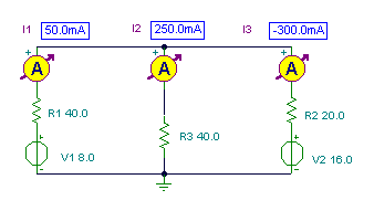


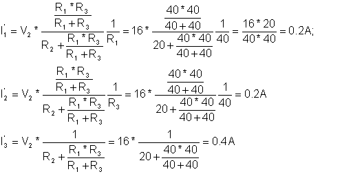
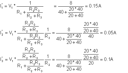
In the first step (left side of the figure above), we calculate the contributions I1’ and I2’ produced by the source V2. In the second step (right side of the figure), we calculate the contributions I1’’ and I2’’ produced by the source V1.
Finding I1’ first, we should calculate R13 (the total resistance of parallel connected R1 and R3) and then use the voltage division rule to calculate V13, the common voltage across these two resistors. Finally, to calculate I1’ (the current through R1), we should use Ohm’s law and divide V13 by R1.





{Use the superposition method!}
{We use doubled subscript because
the Interpreter does not allow the’ and " as an index.
the second subscript means the first or second measuring}
I11:=V2*R1*R3/(R1+R3)/(R2+R1*R3/(R1+R3))/R1;
I21:=V2*R1*R3/(R1+R3)/(R2+R1*R3/(R1+R3))/R3;
I31:=-V2/(R2+R1*R3/(R1+R3));
I12:=-V1/(R1+R2*R3/(R2+R3));
I22:=V1*R2/(R2+R3)/(R1+R2*R3/(R2+R3));
I32:=V1*R3/(R2+R3)/(R1+R2*R3/(R2+R3));
I1:=I11+I12;
I1=[50m]
I2:=I21+I22;
I2=[250m]
I3:=I31+I32;
I3=[-300m]
#We use doubled subscript because
#Python does not allow the ‘ and ” as an index.
#The second subscript means the first or second measuring
I11=V2*R1*R3/(R1+R3)/(R2+R1*R3/(R1+R3))/R1
I21=V2*R1*R3/(R1+R3)/(R2+R1*R3/(R1+R3))/R3
I31=-V2/(R2+R1*R3/(R1+R3))
I12=-V1/(R1+R2*R3/(R2+R3))
I22=V1*R2/(R2+R3)/(R1+R2*R3/(R2+R3))
I32=V1*R3/(R2+R3)/(R1+R2*R3/(R2+R3))
I1=I11+I12
print(“I1= %.3f”%I1)
I2=I21+I22
print(“I2= %.3f”%I2)
I3=I31+I32
print(“I3= %.3f”%I3)
Example 2
Find the voltage V and the current I.


{Using the superposition method !}
I1:=Is*R1/(R1+R1);
I2:=-Vs/(R1+R1)
I:=I1+I2;
I=[0]
V1:=0;
V2:=Vs;
V:=V1+V2;
V=[2]
#Using the superposition method:
I1=Is*R1/(R1+R1)
I2=-Vs/(R1+R1)
I=I1+I2
print(“I= %.3f”%I)
V1=0
V2=Vs
V=V1+V2
print(“V= %.3f”%V)
Example 3
Find the voltage V. 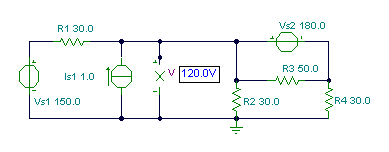
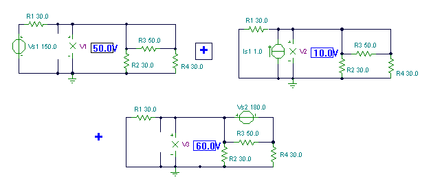


{Using superposition theorem}
V1:=Vs1*R2*R4/(R2+R4)/(R1+R2*R4/(R2+R4));
V1=[50]
V2:=Is1*R2*R4*R1/(R2+R4)/(R1+R2*R4/(R2+R4));
V2=[10]
V3:=Vs2*R1*R2/(R1+R2)/(R4+R1*R2/(R1+R2));
V3=[60]
V:=V1+V2+V3;
V=[120]
#Using superposition theorem:
V1=Vs1*R2*R4/(R2+R4)/(R1+R2*R4/(R2+R4))
print(“V1= %.3f”%V1)
V2=Is1*R2*R4*R1/(R2+R4)/(R1+R2*R4/(R2+R4))
print(“V2= %.3f”%V2)
V3=Vs2*R1*R2/(R1+R2)/(R4+R1*R2/(R1+R2))
print(“V3= %.3f”%V3)
V=V1+V2+V3
print(“V= %.3f”%V)
You can see that using the superposition theorem for circuits containing more then two sources is pretty complicated. The more sources there are in the circuit, the more steps are required. This is not necessarily the case with the other, more advanced methods described in later chapters. If superposition requires you to analyze a circuit three or more times, it is all too easy to mix up a sign or make some other mistake. So if the circuit has more than two sources–unless it is very simple–it is better to use Kirchhoff’s equations and its simplified versions, the methods of nodal voltages or mesh currents described later.
While the superposition theorem can be useful for solving simple practical problems, its main use is in the theory of circuit analysis, where it is employed in proving other theorems.